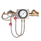
Chemguard In-Line Balanced Pressure Proportioners (ILBP’s) are used with positive displacement foam concentrate pumps and atmospheric foam concentrate storage tanks to form an in-line balanced pressure proportioning system. The Chemguard ILBP is designed to balance the incoming foam concentrate pressure with the incoming water pressure and meter the correct proportion of foam concentrate into the water stream over a wide range of flows and pressures. These units are suitable for use with all types of foam concentrates. The ILBP is a completely self contained device containing all necessary components including the ratio controller, pressure balancing diaphragm valve and duplex pressure gauge. A check valve and manual ball valve are standard on some styles and offered as an optional assembly on other styles.
An ILBP system uses a positive displacement foam concentrate pump to supply foam concentrate to the ILBP. A pressure sustaining (control) valve, located in the return line back to the foam concentrate tank, is set to maintain a regulated pressure to the ILBP which is higher than the pressure of the water supply. The excess foam concentrate not required by the ILPB is returned to the foam concentrate tank through the pressure-sustaining valve. The balancing diaphragm valve senses the foam concentrate pressure and balances it with the water pressure. Balancing is achieved through two sensing lines, one from the water supply, the other from the foam concentrate line. Both lines connect to the balancing valve and a duplex pressure gauge that provides readings for foam concentrate and water pressure. The foam concentrate is then metered through a fixed orifice in the proportioning controller into the water stream.
FEATURES
- UL Listed (All models with 3% AFFF, 4” & 6” models with 3%/6% AR-AFFF @ 3%)
- 5) Standard Sizes available. Three styles are available for each, standard arrangement, straight and manual override straight arrangement.
- 2-1/2” Proportioning Controller has female NPT threaded inlet and male NPT threaded outlet connections
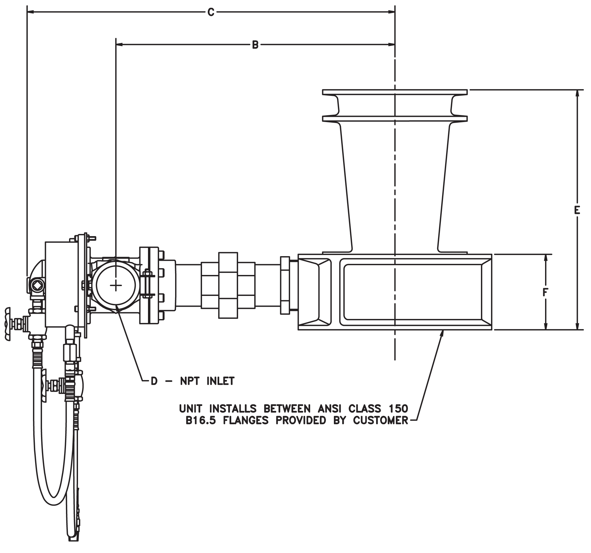
- 3”, 4”, 6” & 8” Proportioning Controllers are designed to fit between two 150 lb. ANSI flanges.
- Balancing diaphragm valve ensures accurate proportioning over a wide flow range.
- Compatible with all Chemguard foam concentratesAll Brass construction with flexible stainless steel braided sensing hoses. Hoses have stainless steel fittings.
FLOW RANGE
Following table lists the nominal flow range for each size ILBP unit. Flow rates for other foam concentrates may vary. Please call for specific application.
| Part No: |
SIZE |
FLOW RANGE (GPM) AR-AFFF |
AFFF |
| CILBP2.5 |
2.5” |
100-350 |
100-400 |
| CILBP3 |
3” |
190-500 |
140-810 |
| CILBP4 |
4” |
390-1300 |
300-1615 |
| CILBP6 |
6” |
650-2900 |
400-3090 |
| CILBP8 |
8” |
1550-4000 |
800-4050 |
DESIGN INFORMATION
To ensure correct operation of the ILBP, Chemguard recommends the pressure of the foam concentrate at the inlet to the ILBP be 20 to 30 psi higher than the water pressure at the ILBP proportioning controller.
The following options are available for the ILBP units.
| -SD |
Standard Style Assembly |
| -ST |
Straight Style Assembly |
| -MO |
Manual Override (Straight) Style Assembly |
| -VS |
Valve Assembly, Straight Style |
| -VM |
Valve Assembly, Manual Override, Straight Style |
| -AF |
3% AFFF foam concentrates |
| -AR |
3%/6% AR-AFFF @ 3% foam concentrate |
| -C2 |
C2 (Veefoam) concentrate |
| -HE |
2% High Expansion foam concentrate |
When ordering a Chemguard ILBP please supply the following information:
- Type and percentage of foam concentrate.
- Minimum and maximum static and residual water inlet pressure available at the proportioning controllers.
- Minimum and maximum foam solution flows expected.
Note:
- Manual Override Style (-MO) not available with Standard Style Assembly (-SD).
- Valve Assembly options (-VS & VM) available for straight style assemblies only. Standard arrangement includes valve assembly.
- Specify desired flow range for –AR option.
- Other foam concentrates available and need to be specified at time of order.
- In-line balanced pressure proportioner systems will proportion slightly higher concentrations at the low end of the nominal flow range.
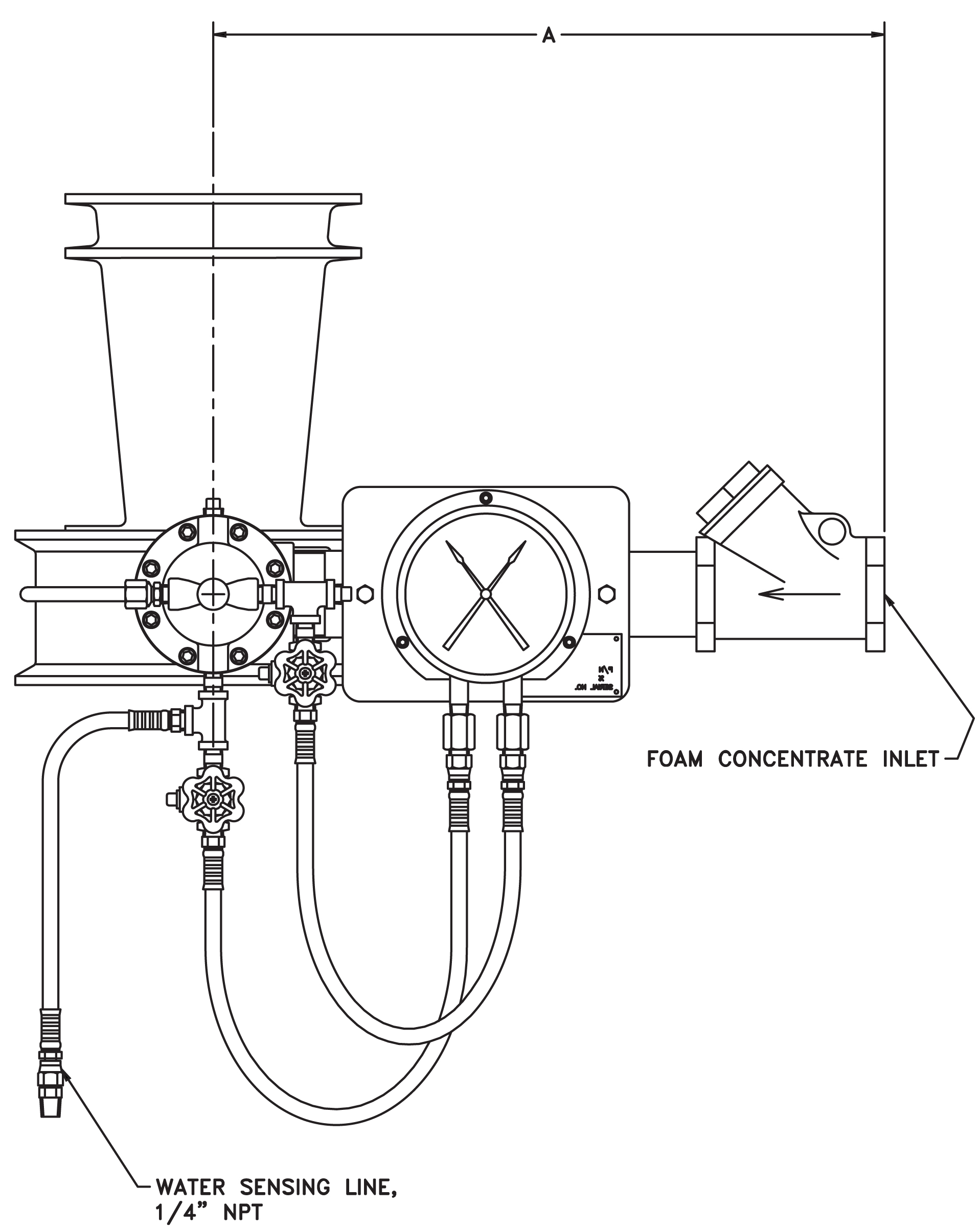
IN-LINE BALANCED PRESSURE PROPORTIONER DIMENSION TABLE
| ILBP Model / Style |
Dimensions |
| A |
B |
C |
D |
E |
| in. |
cm. |
in. |
cm. |
in. |
cm. |
in. |
in. |
| 2.5” Standard Assembly |
10.7 |
27.2 |
23.2 |
58.9 |
6.9 |
17.5 |
1 NPT |
-- |
| 2.5” Straight Assembly |
18.7 |
47.5 |
11.7 |
29.7 |
6.9 |
17.5 |
1 NPT |
1-1/2 NPT |
| 2.5” Manual Override Assembly |
25.2 |
64.0 |
7.7 |
19.6 |
6.9 |
17.5 |
1 NPT |
-- |
| 3” Standard Assembly |
10.9 |
27.7 |
26.6 |
67.6 |
2.5 |
6.4 |
1-1/4 NPT |
-- |
| 3” Straight Assembly |
18.6 |
47.2 |
13.9 |
35.3 |
2.5 |
6.4 |
1-1/4 NPT |
1-1/2 NPT |
| 3” Manual Override Assembly |
27.0 |
68.6 |
9.0 |
22.9 |
2.5 |
6.4 |
1-1/4 NPT |
-- |
| 4” Standard Assembly |
11.5 |
29.2 |
27.3 |
69.3 |
2.8 |
7.1 |
1-1/2 NPT |
-- |
| 4” Straight Assembly |
18.3 |
46.5 |
15.0 |
38.1 |
2.8 |
7.1 |
1-1/2 NPT |
1-1/2 NPT |
| 4” Manual Override Assembly |
27.6 |
70.1 |
10.2 |
25.9 |
2.8 |
7.1 |
1-1/2 NPT |
-- |
| 6” Standard Assembly |
13.1 |
33.3 |
33.9 |
86.1 |
3.3 |
8.4 |
2 NPT |
-- |
| 6” Straight Assembly |
22.9 |
58.2 |
18.4 |
46.7 |
3.3 |
8.4 |
2 NPT |
2-1/2 NPT |
| 6” Manual Override Assembly |
35.0 |
88.9 |
12.1 |
30.7 |
3.3 |
8.4 |
2 NPT |
-- |
| 8” Standard Assembly |
14.3 |
36.3 |
36.3 |
92.2 |
3.6 |
9.1 |
2-1/2 NPT |
-- |
| 8” Straight Assembly |
23.0 |
58.4 |
21.2 |
53.8 |
3.6 |
9.1 |
2-1/2 NPT |
2-1/2 NPT |
| 8” Manual Override Assembly |
38.2 |
97.0 |
14.0 |
35.6 |
3.6 |
9.1 |
2-1/2 NPT |
-- |
Note:
- Reference Ratio Flow Controller Data Sheet for detailed dimensions and minimum recommended length of pipe required upstream and downstream on proportioning controllers.
- Dimensions are approximate.
Note: A Victaulic elbow can be installed in the field on the straight assembly units at the Victaulic coupling.
Technical Drawings