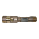
Line proportioners, also termed eductors, present a simple, cost-effective method to proportion foam concentrate and water at the proper percentage. Chemguard offers a full range of line proportioners in corrosion resistant brass. Line proportioners are constant flow devices that produce accurate proportioning of foam concentrate at a specified flow and pressure. It is therefore critical to match the line proportioner with all downstream devices, including all friction loss associated with delivering that flow to the particular discharge device(s) at the design pressure. Line proportioners are usually used in fixed system applications.
For proper operation and to achieve a respectable nozzle operating pressure, line proportioners require inlet pressures in the range of 80 – 200 psi (5.4 – 14 bar), since friction loss through the device is in the order of 35%. Care should also be taken to ensure that the line proportioner is mounted at a maximum of 8-10 ft. (2.4-3.0m) above the minimum expected foam liquid surface.
Line proportioners are typically used in fixed systems where simple and cost effective foam proportioning is required. Other than flowing water, no external power supplies are required to operate line proportioners.
FEATURES
- All brass construction
- Custom flow and pressure options available
- Optional threaded or flanged connections
OPTIONS
- 8 ft. pickup hose with shutoff valve
Technical Drawings
FLOW RATE AT A GIVEN PRESSURE
| Line Proportioner Model |
K Factor Water |
K Factor 3% |
K Factor 6% |
| 120 |
9.2 |
9.5 |
9.8 |
| 210 |
16.1 |
16.6 |
17.1 |
| 240 |
18.4 |
19.0 |
19.6 |
| 280 |
21.5 |
22.2 |
22.9 |
| 350 |
26.9 |
27.7 |
28.6 |
| 420 |
32.2 |
33.2 |
34.3 |
| 480 |
36.8 |
38.0 |
39.2 |
| 550 |
42.2 |
43.5 |
44.9 |
| 600 |
46.1 |
47.5 |
49.0 |
| 660 |
50.7 |
52.2 |
53.9 |
| 730 |
56.0 |
57.8 |
59.6 |
Formula: Q = K *vP
Example: Find flow of model 350 at 180 psi (1241 kPa) when used with 3% foam concentrate.
Model: 350 3%
K Factor: 27.7
Square root of psi x 13.4
Flow Rate: 371 gpm at 180 psi (*1405 lpm at 1241 kPa)
*1 U.S. Gallon = 3.785 Liters
Model |
Dimensions, inches (cm) |
| A |
B |
C |
D |
E |
F |
G |
| 120 |
2-1/2" FNPT |
2-1/2" MNPT |
1" MNPT |
16.13 |
40.97 |
4.38 |
11.13 |
2.75 |
6.99 |
2.50 |
6.35 |
| 210 |
2-1/2" FNPT |
2-1/2" MNPT |
1" MNPT |
16.13 |
40.97 |
4.38 |
11.13 |
2.75 |
6.99 |
2.50 |
6.35 |
| 240 |
2-1/2" FNPT |
2-1/2" MNPT |
1" MNPT |
16.13 |
40.97 |
4.38 |
11.13 |
2.75 |
6.99 |
2.50 |
6.35 |
| 280 |
2-1/2" FNPT |
2-1/2" MNPT |
1" MNPT |
16.13 |
40.97 |
4.38 |
11.13 |
2.75 |
6.99 |
2.50 |
6.35 |
| 350 |
2-1/2" FNPT |
2-1/2" MNPT |
1" MNPT |
16.13 |
40.97 |
4.38 |
11.13 |
2.75 |
6.99 |
2.50 |
6.35 |
| 420 |
2-1/2" FNPT |
3" MNPT |
1" MNPT |
18.38 |
46.69 |
4.50 |
11.43 |
3.11 |
7.90 |
2.75 |
6.99 |
| 480 |
2-1/2" FNPT |
3" MNPT |
1" MNPT |
18.38 |
46.69 |
4.50 |
11.43 |
3.11 |
7.90 |
2.75 |
6.99 |
| 550 |
2-1/2" FNPT |
3" MNPT |
1" MNPT |
18.38 |
46.69 |
4.50 |
11.43 |
3.11 |
7.90 |
2.75 |
6.99 |
| 600 |
3" FNPT |
4" MNPT |
1-1/4" MNPT |
20.50 |
52.07 |
4.50 |
11.43 |
2.72 |
6.91 |
2.75 |
6.99 |
| 660 |
3" FNPT |
4" MNPT |
1-1/4" MNPT |
20.50 |
52.07 |
4.50 |
11.43 |
2.72 |
6.91 |
2.75 |
6.99 |
| 730 |
3" FNPT |
4" MNPT |
1-1/4" MNPT |
20.50 |
52.07 |
4.50 |
11.43 |
2.72 |
6.91 |
2.75 |
6.99 |